1

I am seeing variation between inner and outer spoke tensions on straight pull wheels (3x but no interlacing). The guidance given to me is to have even tension of all spokes on each side of the wheel, and while I can achieve this it seems that a truly balanced wheel would have slightly higher tensions on the inner spokes compared to the outer spokes on the same flange.

My key question is how does this relate to the tangential force the spokes are exerting, as all the inner spokes on both sides are trailing while all the outer are leading. These forces must be equal as the trailing spokes are pulling against the leading spokes and hub will simply rotate to a point where the trailing and leading forces are equal.

It seems to me that the spokes must be providing equal rotational force despite different spoke tensions, because of their different distance from the centre of the hub.

So if I bring the inner and outer spokes on the drive side flange to the same tension I am thinking I must trying to laterally distort the rim, which doesn’t show up because the rims are so stiff? Or perhaps I am compensating with greater variance of tensions on the Non Drive Side of the wheel? I am going to set about measuring a straight pull wheel tensions to see the impact of evening up the tensions on the drive side, as my theory suggests it will be difficult to have even tensions for trailing and leading spokes on each flange. (Drive side flange obviously will be higher than NDS)

2
  • “3x but no interlacing” how is that even possible? Usually the spokes cross, which means they have almost the same angle towards the rim (their “origin” only differs by the width of a spoke, which is <1mm for bladed spokes).
    – Michael
    Commented Oct 2, 2021 at 7:22
  • I mean the inner spokes are not passed over the outside of the outer spokes on the third cross, etc. The inner and outer spokes don’t touch Commented Oct 3, 2021 at 1:02

2 Answers 2

1

So if I bring the inner and outer spokes on the drive side flange to the same tension I am thinking I must trying to laterally distort the rim, which doesn’t show up because the rims are so stiff?

This is correct, although it would actually be trying to distort the rim both laterally and radially.

For most wheels (the exception being a Velomax/Easton type straight pull hub where the spokes are precisely in line with each other on each flange), if the tension was exactly the same and the rim was flexible enough and you had good enough dial indicators on the rim, you could observe the rim distorting around based on this effect.

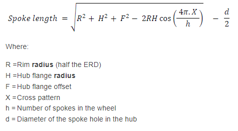
Another way of thinking about it is this: look at the classic spoke length calculation formula

Munson's writing of the spoke length formula

The way most spoke length calculators work, this formula is run once for each side of the hub. But note how simple it is. It takes a simple flange offset number for each flange and conceptualizes that flange as a 2-dimensional circle floating in space. This is a simplification that is only irrelevant most of the time. In reality flanges have thickness, so the spokes on either side have origin points at a different distance from the hub center, and so a more perfect modeling of the wheel would have you run the equation 4 times for most hubs. Your question is not about spoke length calculation, but the reason people don't do that is the same reason they also say to make the tension on each flange the same: most rims are stiff enough and most flanges thin enough to make the effect not matter. Most of the time it's at most a curiosity you can see the evidence only with a dial indicator on a very light, shallow rim. But, start putting the origin points of the pushing and pulling spokes far enough apart on each side of the hub, and/or make the rim flexible enough, and it will start mattering in some situations. Conceptualizing the origin points of the spokes as the same 2-dimensional circle stops working. To make such a wheel with tangential lacing on each side and different offsets for the flanges true to the eye would require 4 different values, one for each group of spokes. Making them be the same as in the spoke length formula's simple model of a hub and rim as triangles and circles is simply making them numerically the same for its own sake, and the wheel will not be true.

Another way of looking at is that it's commonly cited that some amount of deviation from average tension per side is necessary, and the usual reason given is owing to how spokes, rims, and tensiometers all have their imperfections, which is true. But, the fact that the geometry is different on either side of the flange is another reason. If one simply forces the tension values to be the same per side of the hub, the true is going to get worse in a predictable manner, although material imprecision will also be a factor.

0

I think the flange thickness is actually completely irrelevant if the spokes cross before they meet the rim.

You measure the spoke tension on the long stretch between rim and the cross. From the perspective of the rim you could replace the spoke with a force vector which is aligned with the length of the spoke (spokes can pretty much only transmit forces along their length) towards the cross and has a magnitude equal to the spoke tension.

The only difference in angle between spokes is if they cross on the inside or outside. Which is only 1.8mm difference for round spokes and <1mm for bladed spokes.

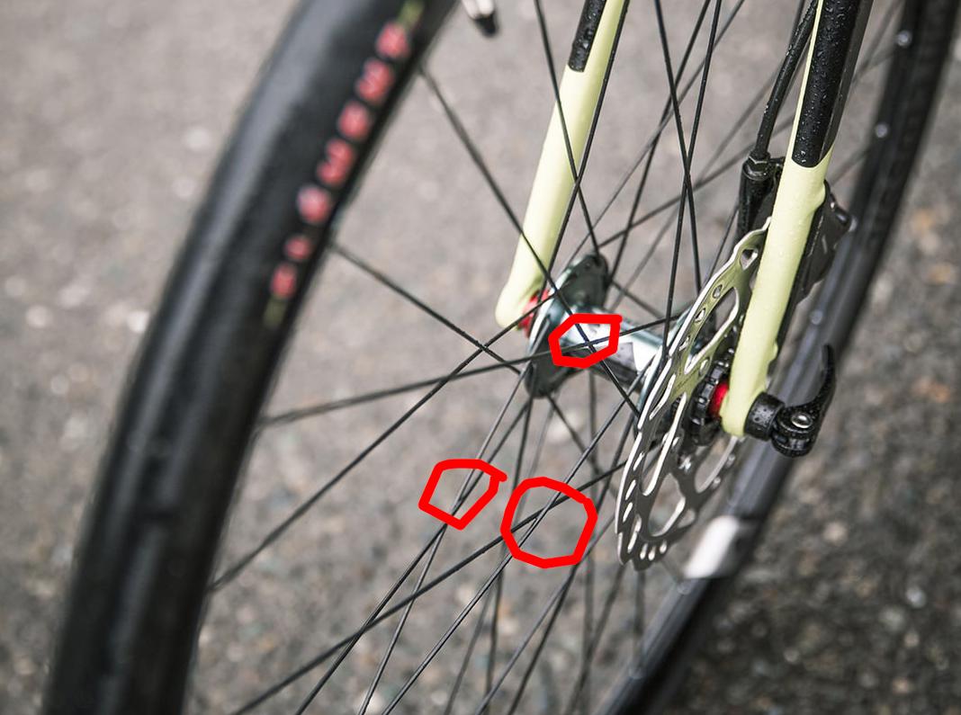
Photo with spoke crossings marked. The flange could be 20mm thick and it wouldn’t affect the rim. photo of bike wheel showing spoke crossings

Your Answer

By clicking “Post Your Answer”, you agree to our terms of service and acknowledge you have read our privacy policy.

Not the answer you're looking for? Browse other questions tagged or ask your own question.