2

If one were to take a single-speed flip-flop hub, and fit two identical freewheels, and couple them to two identical chainrings (i.e. two drive-side cranks, one on each side of the bike), you would have the world's heaviest and least efficient fixed-gear drivetrain. One freewheel coasts while the other drives. (The left-hand pedal would have to be fitted with a right-handed axle, and thread-lock used to prevent it unscrewing due to precession.)

Why anybody would want to do it is beyond me, but I am certain that this would work.

Now, bear with me here...

What if one were to do the same thing, but with a slightly larger chainring on the drive side, and a slightly larger freewheel on the non-drive side? (Obviously magic ratios would have to be selected for identical chain lengths.)

Would this provide a long gear for high top speed, yet provide a shorter gear for less strenuous leg-braking? Or would the freewheels somehow skip and bind?

8
  • 6
    Just how would you expect it to magically shift grears? The are both attached to the same axle. The taller gear is going to be taking the load at all speeds.
    – paparazzo
    Commented Jun 5, 2014 at 13:35
  • I do believe some (very) old bikes used a variation of this scheme to achieve multi(2) speed gearing. Some sort of toggle on the crank selected which ring would be engaged. But very impractical, and not seen in perhaps 80 years. Commented Jun 5, 2014 at 15:00
  • White Industries makes the DOS ENO Freewheel Which is a freewheel with 2 cogs on it that will fit single speed bikes. It allows you to switch between different gears, although you have to loosen the rear wheel to do so.
    – Kibbee
    Commented Jun 5, 2014 at 17:24
  • @Kibbee Nice suggestion, I've seen those before. Really I'm just trying to get my head around this strange idea I had - I won't actually build up a bike like this, just can't figure out the physics of it. Commented Jun 5, 2014 at 17:30
  • 1
    Now I follow. Careful what you ask for. In that set up if you let up the wheel then drives the pedals at faster cadence.
    – paparazzo
    Commented Jun 20, 2014 at 14:25

3 Answers 3

3

They lock up

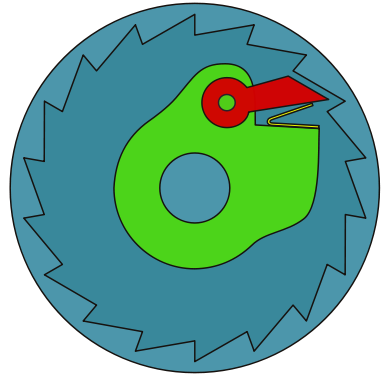
Pawl and teeth

Pretend just 1 pawl and just 1 tooth.

Crank is fixed - left and right chainring spin at same rpm.

Hub is fixed - left and right pawl spin at same rpm.
The green part is attached to the hub that is attached to the wheel.

The teeth are attached to the cogs that are attached to the chain.

Gearing
2:1 left (higher faster) assume 32 chainring and 16 freewheel
1:1 right assume 32 chainring and 32 freewheel

Left freewheel spins at twice the rpm of right. Freewheels are attached to each other via the cogs, chains, chainrings, and crank. They are directly attached - left freewheel must spin at twice the rpm of right.

Both pawl and freewheel are in forward
That little spring is pointed to the front of the bike.
The front wheel is to the left of the picture.
Both pawl start at 12 (of clock).
Left tooth at 12 and engaged.
Right (lower) tooth 3.
Turn the crank 1/4 revolution.
Left higher (2:1) is now at 6.
Right lower is also at 6.
On the right since the pawl (hub) is faster than the freehwheel it slips (coasts).

Freewheel and pawl opposite
Right freewheel and pawl forward (spring pointed to front).
Left freewheel and pawl reverse - (spring point to rear).
Picture is now the right (lower gear) and the front font wheel is to the right.
Left start at 12 engaged.
Right start at 3.
Pedal 1/4 turn.
Left and right are now both at 6.
But now the right does not slip - the right engages.
Both pawls are engaged.
The left is engaged by tooth force on pawl.
The right is engaged by pawl force on tooth.
At this point they lock up.
For every two chain links the right is trying pushing out the left side is only taking one.
The pawls are attach to the same hub.
The left and right side of the hub cannot rotate at a different rpm.

1
  • Thanks Blam! This was exactly the scenario I'd envisaged, but hadn't been able to work out to completion. Commented Jul 9, 2014 at 15:04
3

After thinking about this for awhile, I think this would work, albeit somewhat clumsily. It would operate similar to a retro-direct, except with no reversing for the second freewheel. You would have to use good quality freewheels to avoid having both of them engaging together and binding.

To answer a commenter Blam:

Just how would you expect it to magically shift grears? The are both attached to the same axle.

The two freewheels being engaged in opposite directions would result in only a single freewheel being engaged at a time. He wouldn't be able to 'change' gears, going forward, but would see a different torque profile when slowing down compared to when going forward.

10
  • That was my thinking exactly. But I can't help but feel I'm overlooking some fundamental flaw (other than complete pointlessness). But in the interest of science, next time the missus permits me to acquire some fresh junk, I'm going to try it out. Expect a full report in several years' time :) Commented Jun 6, 2014 at 19:30
  • The "less strenuous leg-braking" implies that one side is set up fixie, freewheel only on the other. As such, I don't think this will do anything for you as the wheel is locked to the fixie and that chain would dominate for all effort. Your answer implies two freewheels. I don't think that will do anything either, but I would want to play with it to see...you would need to build the freewheel "backwards" so unless that already exists, some machining would be needed.
    – Ken Hiatt
    Commented Jun 6, 2014 at 20:42
  • @KenHiatt: the OP indicated two freewheels. Because one would be threaded on 'backwards', it would only engage when the OP tries to coast. So, the two freewheels engaging back and forth would simulate a fixie. Having a 'reverse' freewheel would just be left-side-drive, and that already exists for some BMX bikes and for people with a penchant for novelty-factor. Commented Jun 6, 2014 at 21:35
  • I'd think this would work just fine, until the ratcheting mechanism wears out (which will be a lot quicker than usual, I'd think).
    – Batman
    Commented Jun 7, 2014 at 1:48
  • 2
    Yeah, I suspect a lower gear when riding backwards was not exactly the OP's intention. But it would work. I think it would be funnier to fix both sides and use one of the Shimano "freewheel in the crank" setups so the two pedals rotate at different speeds.
    – Nuі
    Commented Jun 7, 2014 at 5:31
3

This is my mental experiment on this.

The O.P. states he would install a bigger cog on the left, and a bigger chainring on the right, resulting on a higher (faster) gear ration on right side and a lower(slower) gear ratio on the left.

Now, if the freewheel is installed normally (i.e. freewheeling on coast) then this happens:

If the freewheel is on the higher gear side, then it wants to move the bike faster, but the fixed side wants to go slower, so the transmission seizes.

If the freewheel is on the lower gear side, then the fixed side would move the bike faster than the freewheel side, so this side is actually coasting while the fixed side does the real work. Now you start trying to slow down, but the fixed side is always engaged, so the freewheel side never gets to be in use.

Second try: Somewhow the Freewheel is installed backwards, so it freewheels when you pedal forward, but engages on backpedalling:

If the freewheel is in the higher gear side: when you pedal forward the bike moves with the low gear ratio in the fixed side, the higher side freewheels because the hub rotates slower than the freewheel cog. Now stop pedalling, the frewheeling side engages so the tire tries to move the crankset and since it has higher ratio it tries to move the crankset slower than what the fixed side tries to move it, the transmission seizes.

If the freewheel is in the lower gear ratio side: When pedalling forward the fixed side dives the bike with the highest (fastest) ratio, the hub rotates forward faster than what the lower ratio tries to, the freewheel sees this as backpedaling (crankset rotating slower than the hub) so the transmision seizes.

I think that such arrangement woul not work, instead it would create potential catastrophic failure of the components due to them trying to drive one another with different angular speeds. However, I don't think the idea is to be dismissed, I think the goal of having one one ratio to accelerate and other to brake is to use two differently sized freewheels installed to engage in different directions. For this experiment I'd rather install a dual crankset with two identical chainrings.

Option 1: small freeweel engages while pedalling forward. The bike moves forward when pedalling normally using the higher ratio, then when trying to coast, the small cog starts freewheeling and the larger one engages, trying to move the crankset a little bit faster. When it does, it might result on a temporary engagement of the small freewheel that depends on an obscure relation between the angular position of the pawls inside the two ratchets, but as you are trying to slow down the pedals, the process repeats until you come to a stop (maybe a very jerky one). Whether or not this works whould depend on how much each freeweel can rotate before engaging (i.e. how long the ramps are) compared to the difference in gear ratios between them.

Option 2: big freeweel engages while pedalling forward. The bike moves moves forward using the lower ratio, the smaller cog is reverse-installed so ir freewheels. When trying to slow down the small freewheel engages, making the crankset rotate but slower than the ratio of the big freewheel demands, so it won't engage. This would give you different ratios for accelerating and braking, but would not satify the O.P. desire to have the lower ratio for braking.

Feel free to comment any corrections, I'd be happy to edit accordingly.

3
  • I think I agree with Option 1. You would hammer between the two pawls.
    – paparazzo
    Commented Jul 8, 2014 at 16:42
  • OK I don't agree with Option 1 but still +1 as it got me to think in terms of speed not torque.
    – paparazzo
    Commented Jul 9, 2014 at 18:51
  • I think this is actually the correct answer, assuming a fixed/free combo (which would be easiest to build if you put the fixed cog on the normally non-drive side, since it's designed to be driven 'backwards' as it is here)
    – Móż
    Commented Oct 21, 2015 at 23:51

Your Answer

By clicking “Post Your Answer”, you agree to our terms of service and acknowledge you have read our privacy policy.

Not the answer you're looking for? Browse other questions tagged or ask your own question.