There is a tool call a disc brake tab facing tool.
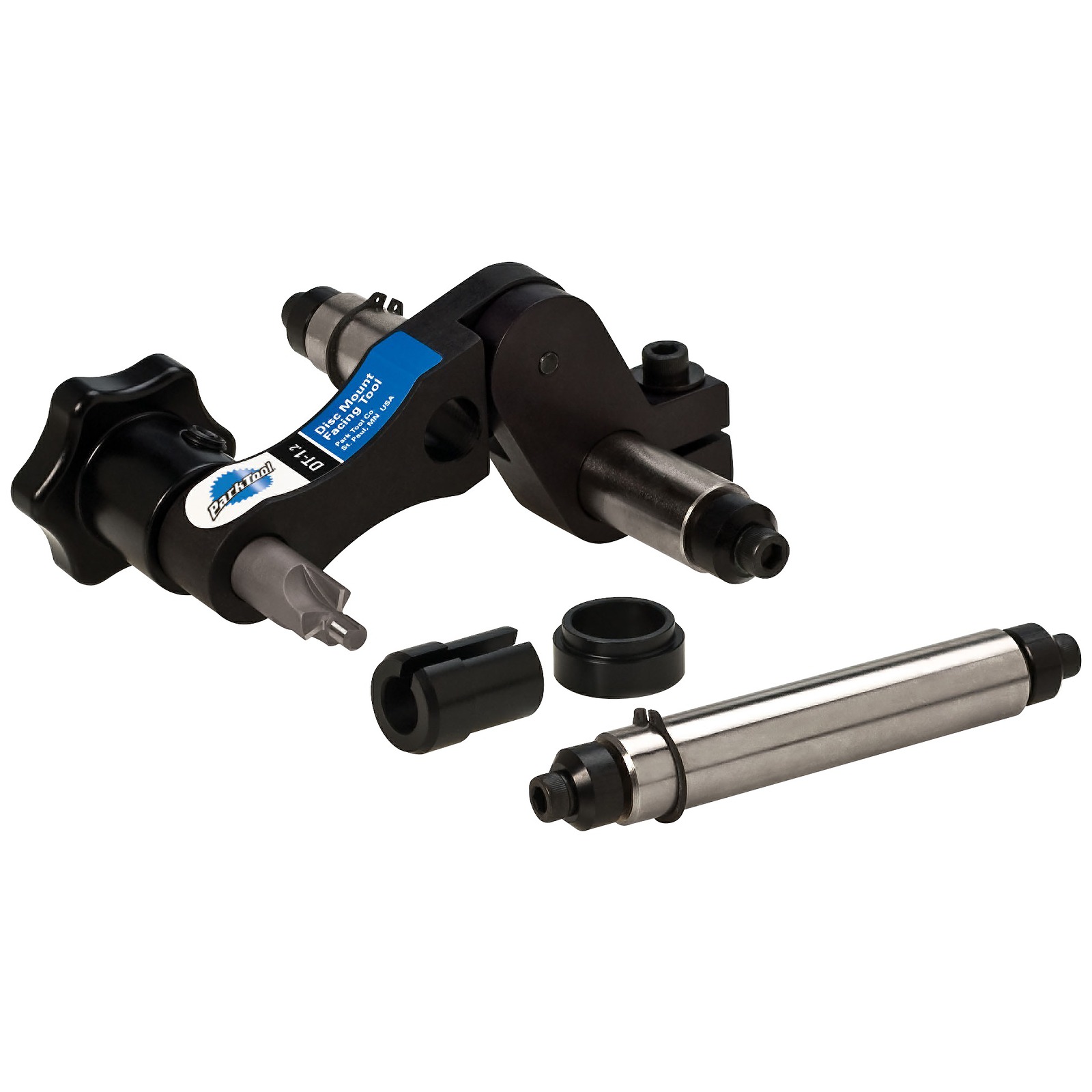
This tool is designed to correct the alignment of IS disc brake tabs with the dropouts of the frame, so that the rotor will be correctly aligned with the caliper.
See instructions below from Park Tool Repair Help Blog:
Disc Brake Mount Facing (IS type) with DT-1
This article will discuss the use the Park Tool DT-1 Disc Brake Mount Facing Tool. The DT-1 is a precision tool system designed to machine disc brake mounts flat, parallel, and in the same plane. Use of the DT-1 helps ensure proper disc brake setup and performance.
The DT-1 includes everything needed to face the disc brake mounts on frames using 10mm axles and forks using 9mm axles. It also includes special adapter bushings to allow facing of disc brake mounts on frames using 12mm through axles and forks using 20mm through axles.
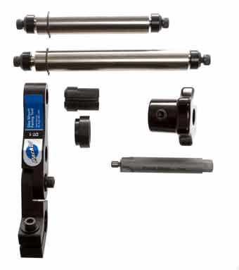
Being a precision cutting tool, the DT-1 should be used and stored with extreme care. Always liberally apply cutting fluid (we recommend Park Tool CF-2 Cutting Fluid) to the brake mount and cutting teeth of the facer during each use. Components should be kept clean and the facing cutter should be periodically wiped with an oily cloth or rust inhibitor before storage, especially in a damp or humid environment. Store the DT-1 in its original packaging or other safe location. Like all cutting tools, the facing cutter included with the DT-1 should be periodically replaced or sharpened by a qualified technician.
Installation of tool:
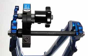
135mm Rear Frames: Insert the longer axle into the body of the DT-1. The axle pinch bolt should face to the back. The side of the axle with the C-clip goes to the dropout side. Install the axle fully into frame and secure axle. NOTE: Bikes with 130mm spacing will easily flex open to accept the 135mm axle for purposes of facing.
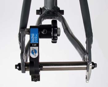
135mm frame with 10mm axle.
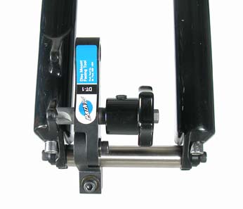
100mm Forks with 9mm Axles: Insert the shorter axle into the body of the DT-1. The axle pinch bolt should face to the back. The side of the axle with the C-clip goes to the dropout side. Install the axle fully into frame and secure axle.
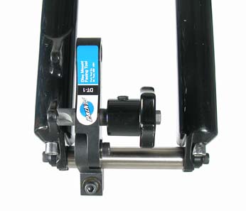 100mm wide fork, with 9mm axle.
12mm Axle Rear frame: Insert axle through left side dropout, through 12mm ID spacer, and through DT-1 body. Smaller end of spacer fits into body of DT-1. Secure frame axle. Push body of DT-1 to the left until spacer contacts dropout. Secure axle pinch bolt.
 12mm rear through axle with DT-1.
20mm Through Axle Forks: Insert axle through side dropout, through body of DT-1 and through 20mm ID spacer. Smaller end of spacer faces left side of fork (disc mount side). Push body of DT-1 to left until spacer contacts dropout. Secure axle pinch bolt.
 20mm through axle with spacer.
Facing Procedure:
- Assemble DT-1 into bike as described above.
- Loosen knob setscrew. Slide knob to end of facing cutter shaft, next to 10mm hex. Tighten knob setscrew.
- Loosen pinch bolt and pivot bolt just enough to allow lower body and upper body to pivot and slide on axle.
- Slide body against retaining ring or bushing.
- Insert cutter through lower hole of body. Insert piloted tip of cutter fully into hole of brake mount.
- Tighten pinch bolt and pivot bolt to lock position.
- Turn knob clockwise while applying hand pressure to face surface of brake mount. Remove only enough material to create a clean, flat cut around the face of the mount. NOTE: For speed and leverage, a ratcheting wrench with a 10mm socket can be used to turn the 10mm hex head on the cutter .
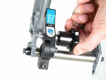
- With teeth of cutter contacting face of brake mount, loosen knob setscrew and slide knob on shaft of cutter until contact is made with body. Tighten setscrew.
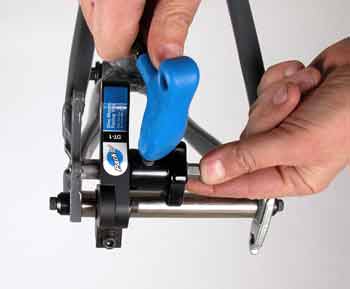
- Pull knob and cutter from lower hole and insert through upper hole. Loosen pinch bolt and/or pivot bolt to fit piloted tip of cutter fully into hole of brake mount, then retighten.
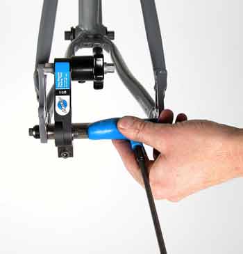
Note position of cutter teeth. If cutter teeth contact brake mount and there is gap between knob and body, complete facing and stop. If knob contacts body before cutter teeth contact brake mount, OR, if knob contacts body at the same time cutter teeth contact brake mount, reset the tool as in step 3, and face the upper mount. Use this setting to then face the lower mount.
- Turn knob clockwise while applying hand pressure to face surface of disc mount. Continue facing mount until knob stops against body. The facing process is complete. The upper and lower mounts should have a clean, flat cut and the faces should be parallel and in the same plane. Remove DT-1 from frame.
NOTES ON DT-1 USE:
Like all machining, use a cutting fluid such as Park Tool CF-2. If there is some "chatter" on the surface, the cut will still be square to the axle and the brake will mount properly to the disc. Change the amount of pressure and speed of the cutter to reduce chatter.
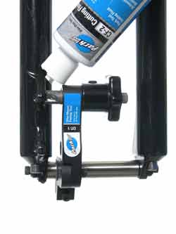 Use a cutting fluid such as CF-2.
When cutting the surface of the disc mount, it is important to achieve a flat surface for the brake mount. In the image below, both mounts are adequately faced. Notice the left and right mount do not look identical. However, if the two mounts were faced to the same reference on the cutter, the job is done.
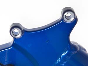 Adequately machined caliper mounts.
It is important to note the "foot print" left by the cutter and compare this to the "foot print" or contact area of the caliper body or caliper body bracket adapter. Some mounts require significant machining, and the size of the machined surface may be smaller than the bracket.
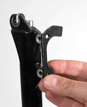
The adapter bracket above will have a larger contact area then the machined surface. Use spacers in this case.
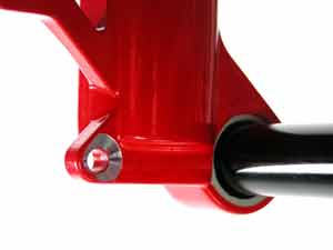
Close up of a machined cut likely to need spacing.
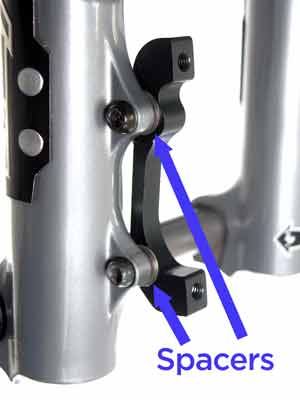 Spacers in place for the adapter bracket.
If the caliper mount is equal to or smaller than the machined area, no spacer is required.
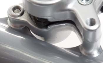
This disc mount-to-caliper interface will not require a spacer.


 100mm wide fork, with 9mm axle.
 12mm rear through axle with DT-1.
 20mm through axle with spacer.


 Use a cutting fluid such as CF-2.
 Adequately machined caliper mounts.

 Spacers in place for the adapter bracket.