I'm pro-actively replacing the chain on my son's bike (the first time I neglected this cost me dear for replacement of derallieur, cassette and cranks at the LBS) which is used daily for commute to school (about 8.5 miles/day round trip). The previous chain was a KMC which came with a quick-link, this time I am back to the original.
The new chain is Shimano 8S CN-HG71, and comes with a connecting pin rather than quick-link. I'm looking at the Dealers Manual DM-GN0001-23-ENG.pdf pages 68 onwards. I have all the necessary tools.
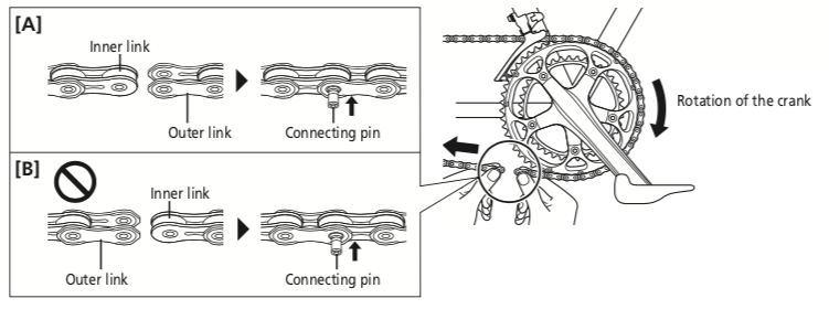
On page 70 it states: As illustrated in Fig. [A], we strongly recommend to set the connecting pin in the hole of the outer link on the front side in the direction of travel. The chain’s level of strength is enhanced compared to the method in Fig. [B]
This is accompanied by an image but unfortunately, rather than clarify, this has left me with a level of doubt.
The picture shows the chain broken below the crank therefore travelling right-to-left, if the figs. [A] and [B] correspond to this then they are the opposite way around to what the words suggest. Or is the pulling-force being applied from the right-hand-end of those diagrams (so they are not a direct zoom-in to the crank diagram, despite that being suggested)?
Image credit: Shimano

